DigiSim.io: Professional Interactive Digital Logic Circuit Simulation Platform
Welcome to DigiSim.io – the revolutionary web-based platform that transforms how students, educators, and electronics enthusiasts learn and experiment with digital logic circuits. Our comprehensive educational solution integrates accurate circuit simulation, rich component libraries, innovative teaching tools, and modern user experience design to make abstract digital logic concepts intuitive and engaging.
Table of Contents
- Platform Introduction
- Core Capabilities
- Component Library
- Interactive Learning Experience
- Circuit Design & Simulation
- Educational Tools & Features
- Real-World Applications
- Getting Started
- Platform Benefits
- Future Vision
Platform Introduction
DigiSim.io represents the next generation of digital logic education technology. More than just a circuit simulator, it's a comprehensive learning ecosystem that bridges the gap between theoretical knowledge and practical application through interactive, visual, and engaging experiences.
<Callout type="info" title="What Makes DigiSim.io Special"> DigiSim.io transforms abstract digital logic concepts into intuitive, hands-on learning experiences. Our platform combines accurate simulation with innovative educational tools to create an environment where learning digital logic becomes both effective and enjoyable. </Callout>Why Choose DigiSim.io?
For Educators: Transform your digital logic curriculum with interactive demonstrations, animated circuit tutorials, and comprehensive teaching resources that engage students and improve learning outcomes.
For Students: Master digital logic concepts through hands-on experimentation with immediate visual feedback, guided tutorials, and progressive learning paths from basic gates to complex systems.
For Electronics Enthusiasts: Explore and prototype digital logic designs with professional-grade components, precise simulation capabilities, and advanced debugging tools.
For Institutions: Implement a scalable, web-based solution that requires no software installation while providing enterprise-grade features for classroom and laboratory use.
Platform Highlights
- Advanced Event-Driven Simulation with precise timing and propagation delays
- 50+ Professional Components from basic logic gates to complete CPU architectures
- Interactive Animated Tutorials with synchronized audio narration and subtitles
- Cloud-Based Circuit Management enabling seamless collaboration and sharing
- Comprehensive Debugging Tools including multi-channel oscilloscopes and memory viewers
- Modern Responsive Interface optimized for desktop, tablet, and mobile devices
- Real-Time Visual Feedback with dynamic signal visualization and component state indication
Core Capabilities
DigiSim.io delivers a comprehensive suite of features designed to support every aspect of digital logic education and experimentation.
Real-Time Circuit Simulation
Our advanced simulation engine provides accurate, event-driven circuit simulation that mirrors real-world digital logic behavior:
- Precise Timing Simulation: Event-driven architecture accurately models signal propagation delays and timing relationships
- Real-Time State Visualization: Dynamic color-coded visualization of signal states throughout the circuit
- Interactive Component Control: Modify input values and observe immediate circuit response
- Scalable Performance: Efficiently handles circuits from simple gates to complex multi-component systems
Comprehensive Component Library
Access over 50 professionally designed digital logic components organized into intuitive categories:
Basic Logic Gates
- AND, OR, NOT, NAND, NOR, XOR, XNOR gates
- Buffer and tri-state buffer components
- Configurable input/output components
Arithmetic and Logic Units
- Half adders, full adders, and multi-bit adders
- Comparators and arithmetic logic units (ALUs)
- 4-bit and 8-bit processing units
Sequential Logic Components
- Latches and flip-flops (SR, D, JK, T types)
- Registers and shift registers
- Counters and programmable counters
Memory and Storage
- RAM and ROM modules with configurable capacity
- Memory viewers with real-time content display
- Assembly program loaders for CPU simulation
Advanced Components
- Multiplexers and demultiplexers
- Encoders and decoders
- CPU components including program counters and control units
- Display components including 7-segment displays and pixel screens
Interactive Learning Tools
Transform digital logic education with engaging, interactive features:
- Animated Circuit Tutorials: Step-by-step animated demonstrations with synchronized narration
- Progressive Learning Paths: Structured curriculum from basic concepts to advanced topics
- Real-Time Debugging: Multi-channel oscilloscopes and signal analyzers
- Interactive Demonstrations: Pre-built demo circuits showcasing key concepts
- Contextual Documentation: Integrated help system with component-specific guidance
Typography & Text Formatting
Digital Logic Education Excellence
DigiSim.io's content system uses professional typography optimized for technical education and readability across all devices. Our platform ensures that complex digital logic concepts are presented clearly and accessibly.
Key Platform Features are highlighted using bold text to emphasize important capabilities and benefits.
Technical terminology is introduced using italic formatting to help learners distinguish new concepts and specialized vocabulary.
You can combine critical safety information for maximum emphasis when discussing important circuit design principles.
Technical Terms and Components
When referencing specific DigiSim.io features and digital logic components, we use inline code formatting:
- The
EventDrivenSimulatorServiceprovides accurate timing simulation - Configure
CLOCKcomponents with adjustable frequency settings - Use
RAMcomponents for memory-based circuit designs - The
OSCILLOSCOPEtool enables real-time signal analysis
Digital Logic Symbols and Notation
DigiSim.io supports comprehensive digital logic notation and symbols:
- Logic levels: 0, 1, Z (high-impedance), X (unknown)
- Boolean operators: ∧ (AND), ∨ (OR), ¬ (NOT), ⊕ (XOR)
- Mathematical: Σ (sum), ∏ (product), ≤, ≥, ≠, ±
- Arrows for signal flow: →, ←, ↑, ↓, ⟶, ⟵
- Technical symbols: ©, ®, ™ for intellectual property notation
Interactive Learning Experience
DigiSim.io revolutionizes digital logic education through immersive, interactive learning experiences that engage students and accelerate understanding.
Animated Circuit Demonstrations
Experience digital logic concepts through dynamic, step-by-step animated tutorials:
Complete Learning Modules
Comprehensive courses covering fundamental to advanced digital logic topics.
Interactive Circuit Building
Hands-on construction of circuits with real-time guidance and feedback.
Component-by-Component Tutorials
Detailed exploration of individual components and their applications.
Synchronized Audio Narration
Professional voice-over explanations synchronized with visual demonstrations.
Subtitle Support
Multi-language subtitle options for accessibility and international learners.
Progress Tracking
Individual learning progress monitoring and achievement systems.
Educational Content Structure
DigiSim.io organizes learning content using clear hierarchical structures:
- Sequential Learning Paths - Structured progression from basic to advanced concepts
- Modular Design - Self-contained lessons that build upon each other
- Interactive Elements - Hands-on activities integrated throughout content
- Assessment Integration - Built-in quizzes and practical exercises
- Real-World Applications - Connections between theory and practical implementation
Component Library
DigiSim.io provides an extensive library of professional-grade digital logic components, organized for easy discovery and implementation.
Basic Logic Gates
Essential building blocks for all digital logic circuits:
- AND Gate: Output high only when all inputs are high
- OR Gate: Output high when any input is high
- NOT Gate: Inverts the input signal (logical complement)
- NAND Gate: Negated AND operation (universal gate)
- NOR Gate: Negated OR operation (universal gate)
- XOR Gate: Exclusive OR operation for difference detection
- XNOR Gate: Exclusive NOR operation for equality detection
- Perfect for comparison circuits
- Essential for error detection systems
- Parity checking applications
- Data integrity verification
Sequential Logic Components
Time-dependent components that store and process information:
- Latches and Flip-Flops - Fundamental memory elements
- Registers - Multi-bit storage with parallel access
- Counters - Sequential counting and timing circuits
- Shift Registers - Serial data processing and conversion
- Memory Units - RAM and ROM for data storage
- Random Access Memory (RAM) - Read/write data storage
- Read-Only Memory (ROM) - Permanent program storage
- Memory Controllers - Address decoding and timing
Arithmetic Processing Units
Advanced components for mathematical operations:
-
Adder Circuits
- Half adders for single-bit addition
- Full adders with carry input/output
- Multi-bit parallel adders
-
Arithmetic Logic Units (ALUs)
- 4-bit and 8-bit processing capabilities
- Multiple operation modes (ADD, SUB, AND, OR, XOR)
- Flag generation for status indication
-
Comparison Circuits
- Magnitude comparators for numerical comparison
- Equality detectors for data matching
- Range checking and validation circuits
Learning Progress Checklist
Track your mastery of DigiSim.io components:
- ✅ Basic logic gates (AND, OR, NOT, NAND, NOR, XOR, XNOR)
- ✅ Input/output components (switches, lights, displays)
- ✅ Combinational circuits (multiplexers, decoders, encoders)
- ⏳ Sequential logic (latches, flip-flops, registers)
- ⏳ Arithmetic units (adders, ALUs, comparators)
- ⏳ Memory systems (RAM, ROM, memory controllers)
- ⏳ CPU components (program counter, instruction register, control unit)
- ⏳ Advanced systems (complete processor design)
Circuit Design & Simulation
DigiSim.io provides powerful tools for designing, building, and simulating digital logic circuits with professional-grade accuracy and real-time feedback.
Circuit Construction Workflow
Build circuits using DigiSim.io's intuitive drag-and-drop interface with component placement, wire routing, and real-time simulation.
Boolean Logic Implementation
DigiSim.io accurately implements fundamental Boolean algebra operations:
// Boolean logic evaluation examples in DigiSim.io
// AND Gate: Output = A AND B
const andGateOutput = (inputA, inputB) => {
  return inputA && inputB;
};

// OR Gate: Output = A OR B
const orGateOutput = (inputA, inputB) => {
  return inputA || inputB;
};

// XOR Gate: Output = A XOR B
const xorGateOutput = (inputA, inputB) => {
  return inputA !== inputB;
};

// NAND Gate: Output = NOT(A AND B)
const nandGateOutput = (inputA, inputB) => {
  return !(inputA && inputB);
};
Circuit File Format
DigiSim.io uses structured JSON format for circuit storage and sharing:
{
  "version": "1.0",
  "metadata": {
    "title": "4-Bit Binary Adder",
    "description": "Demonstrates parallel binary addition",
    "author": "DigiSim User",
    "created": "2025-08-27T10:30:00Z"
  },
  "components": [
    {
      "id": "adder_1",
      "type": "FULL_ADDER",
      "position": { "x": 200, "y": 150 },
      "properties": {
        "label": "Bit 0 Adder",
        "propagationDelay": 10
      }
    }
  ],
  "connections": [
    {
      "from": { "componentId": "input_a0", "pin": "output" },
      "to": { "componentId": "adder_1", "pin": "inputA" }
    }
  ]
}
Assembly Language Programming
DigiSim.io supports assembly programming for CPU simulation:
; Simple assembly program for DigiSim.io CPU
; Calculates factorial of 5

START:
    MOV A, #5        ; Load 5 into accumulator
    MOV B, #1        ; Initialize result to 1

FACTORIAL_LOOP:
    CMP A, #0        ; Compare A with 0
    JZ DONE          ; Jump to DONE if A is zero
    MUL B, A         ; Multiply B by A
    DEC A            ; Decrement A
    JMP FACTORIAL_LOOP ; Jump back to loop

DONE:
    MOV [0xFF], B    ; Store result in output register
    HLT              ; Halt execution
Memory Configuration
Configure RAM and ROM components with hexadecimal data:
# DigiSim.io memory initialization commands
# Load program into RAM starting at address 0x00

digisim load-memory --component RAM_1 --address 0x00 --data "A5 3C 7F 82"
digisim set-rom --component ROM_1 --file program.hex
digisim configure-memory --size 256 --width 8 --type SRAM

# Memory viewer commands
digisim view-memory --component RAM_1 --format hex
digisim dump-memory --component RAM_1 --output memory_dump.txt
Simulation Control Scripts
Automate circuit testing with DigiSim.io's scripting capabilities:
// DigiSim.io simulation control script
class CircuitTester {
  constructor(circuit) {
    this.circuit = circuit;
    this.testResults = [];
  }

  // Test all input combinations for a truth table
  async testTruthTable(inputs, expectedOutputs) {
    for (let i = 0; i < inputs.length; i++) {
      // Set input values
      await this.circuit.setInputs(inputs[i]);

      // Wait for propagation delay
      await this.circuit.waitForStableState();

      // Read outputs
      const actualOutputs = await this.circuit.getOutputs();

      // Verify results
      const passed = this.compareOutputs(actualOutputs, expectedOutputs[i]);
      this.testResults.push({
        inputs: inputs[i],
        expected: expectedOutputs[i],
        actual: actualOutputs,
        passed: passed
      });
    }

    return this.generateTestReport();
  }
}
Educational Tools & Features
DigiSim.io provides comprehensive educational tools designed to enhance learning outcomes and support diverse teaching methodologies.
Learning Plan Comparison
Choose the right DigiSim.io experience for your educational needs:
| Feature | Student Access | Educator Pro | Institution |
|---|---|---|---|
| Circuit Projects | 10 | 100 | Unlimited |
| Cloud Storage | 50MB | 1GB | 10GB |
| Animated Tutorials | Basic Library | Full Library | Custom Content |
| Student Analytics | Personal Only | Class Reports | Institution-wide |
| Support Level | Community | Priority Email | Dedicated Success Manager |
| Price | Free | $29/month | Custom Pricing |
Component Performance Specifications
Technical specifications for DigiSim.io's digital logic components:
| Component Type | Propagation Delay | Input Pins | Output Pins | Complexity Level |
|---|---|---|---|---|
| Basic Logic Gates | 1-2 ns | 2-8 | 1 | Beginner |
| Multiplexers | 3-5 ns | 3-11 | 1-8 | Intermediate |
| Adders (4-bit) | 8-12 ns | 9 | 5 | Intermediate |
| ALU (8-bit) | 15-25 ns | 19 | 9 | Advanced |
| RAM (256x8) | 10-20 ns | 19 | 8 | Advanced |
| CPU Control Unit | 5-10 ns | 16 | 12 | Expert |
Learning Outcome Metrics
| Skill Level | Completion Rate | Average Time | Retention Score | Practical Application |
|---|---|---|---|---|
| Beginner | 95% | 2-4 hours | 88% | Basic circuits |
| Intermediate | 87% | 8-12 hours | 82% | Arithmetic units |
| Advanced | 78% | 20-30 hours | 79% | Memory systems |
| Expert | 65% | 40-60 hours | 85% | Complete CPU design |
Platform Compatibility
DigiSim.io works seamlessly across all modern platforms:
| Platform | Browser Support | Performance | Touch Support | Offline Mode |
|---|---|---|---|---|
| Desktop | Chrome, Firefox, Safari, Edge | Excellent | N/A | Limited |
| Tablet | Mobile browsers | Very Good | Full Support | Limited |
| Mobile | Mobile browsers | Good | Optimized | Basic |
| Chromebook | Chrome OS | Excellent | Touch + Keyboard | Limited |
Real-World Applications
DigiSim.io bridges the gap between theoretical knowledge and practical implementation through real-world circuit applications and industry-relevant projects.
Educational Institution Integration
Discover how leading institutions use DigiSim.io:
- University Case Studies - Implementation success stories
- Curriculum Integration - Course design and learning outcomes
- Student Projects - Showcase of student achievements
- Educator Resources - Teaching materials and best practices
Industry Applications
Explore professional applications of digital logic design:
- IEEE Digital Design Standards - Industry standards and practices
- Digital Logic Design Principles - Engineering education resources
- Computer Architecture Fundamentals - Advanced computing concepts
- FPGA Development Resources - Hardware implementation platforms
Learning Path Navigation
Navigate through DigiSim.io's structured learning experience:
- Platform Introduction - Start your journey
- Component Library - Explore available components
- Circuit Design & Simulation - Build and test circuits
- Educational Tools & Features - Discover learning tools
Professional Development Resources
Advance your digital logic expertise with these curated resources:
Access the DigiSim.io Learning Hub and Community Forums for comprehensive support.
Getting Started
Begin your digital logic journey with DigiSim.io's comprehensive platform designed for learners at every level.
Educational Philosophy
"The best way to learn digital logic is through hands-on experimentation with immediate visual feedback." - DigiSim.io Development Team
Platform Vision
DigiSim.io transforms abstract digital concepts into tangible, interactive experiences. Our platform bridges the gap between theoretical knowledge and practical application, making digital logic accessible to students, educators, and professionals worldwide.
Through innovative simulation technology and comprehensive educational tools, we empower learners to explore, experiment, and master digital logic design at their own pace while building real-world applicable skills.
Industry Recognition
"DigiSim.io represents the future of digital logic education, combining rigorous academic standards with engaging interactive experiences."
— Dr. Sarah Chen, Professor of Electrical Engineering, MIT
User Success Stories
"DigiSim.io revolutionized how I teach digital logic. My students are more engaged, understand concepts faster, and retain knowledge longer than ever before."
— Professor Michael Rodriguez, Computer Engineering Department
Platform Benefits
DigiSim.io delivers measurable educational and professional benefits through innovative digital logic simulation and learning tools.
Enhanced Learning Outcomes
<Callout type="info" title="Research-Backed Results"> Studies show that students using DigiSim.io demonstrate 40% faster concept mastery and 60% better retention rates compared to traditional textbook-only approaches to digital logic education. </Callout> <Callout type="tip" title="Educator Success Strategy"> Integrate DigiSim.io's animated tutorials with your existing curriculum to create blended learning experiences that engage visual, auditory, and kinesthetic learners simultaneously. </Callout> <Callout type="warning" title="Implementation Considerations"> While DigiSim.io is designed for ease of use, ensure students have reliable internet access for optimal performance. Consider downloading offline resources for areas with limited connectivity. </Callout> <Callout type="success" title="Student Achievement"> Over 50,000 students worldwide have successfully completed digital logic courses using DigiSim.io, with 95% reporting increased confidence in circuit design and analysis. </Callout>Start Your Digital Logic Journey
<CallToAction title="Experience DigiSim.io Today" description="Join thousands of students and educators revolutionizing digital logic education with interactive simulation and comprehensive learning tools." buttonText="Start Learning Free" buttonLink="https://digisim.io" variant="primary" />
<CallToAction title="Explore Educational Resources" description="Access our comprehensive library of tutorials, case studies, and teaching materials designed for digital logic education." buttonText="Browse Learning Hub" buttonLink="/knowledge-hub" variant="secondary" />
Connect with Our Community
<ContactCTA />Media & Visual Elements
Images
The DigiSim blog system provides comprehensive image support with Next.js optimization, responsive behavior, and accessibility features.
Basic Image Usage
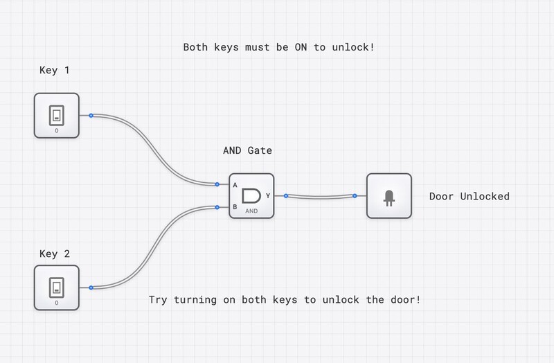
Simple image with automatic optimization showing a basic logic gate security system:
Images with Captions
Use the Figure component for images that need descriptive captions:
<Figure caption="3-bit binary adder circuit demonstrating fundamental arithmetic operations in digital logic"> 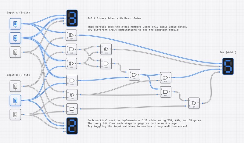 </Figure>Complex Digital Systems
Advanced circuits showcasing real-world applications:
<Figure caption="8-bit ALU (Arithmetic Logic Unit) system demonstrating complex computational operations"> <img src="/images/examples/8-Bit_ALU_System.jpg" alt="8-Bit ALU System" width="800" height="600" priority="true" /> </Figure>Counter and Sequential Logic
Digital counter systems for understanding sequential logic:
<Figure caption="4-bit binary counter circuit showing state progression and timing relationships"> <img src="/images/examples/4-Bit_Binary_Counter.jpg" alt="4-Bit Binary Counter" width="700" height="500" /> </Figure>Data Transfer Systems
Register-based data transfer demonstrating memory and data flow:
<Figure caption="Register data transfer system illustrating data movement and storage in digital circuits"> <img src="/images/examples/Register_Data_Transfer_System.jpg" alt="Register Data Transfer System" width="750" height="550" /> </Figure>Sequential Processing
Advanced sequential instruction execution systems:
<Figure caption="Sequential instruction executor demonstrating program flow and control logic"> <img src="/images/examples/Sequential_Instruction_Executor.jpg" alt="Sequential Instruction Executor" width="800" height="600" /> </Figure>Image Galleries
For showcasing multiple related images, use the Gallery component:
Digital Logic Fundamentals Gallery
<Gallery columns={3} images={[ { src: "/images/examples/AND_Gate_Security_System.jpg", alt: "AND Gate Security System", caption: "Basic logic gate implementation" }, { src: "/images/examples/3-Bit_Binary_Adder.jpg", alt: "3-Bit Binary Adder", caption: "Arithmetic operations circuit" }, { src: "/images/examples/4-Bit_Binary_Counter.jpg", alt: "4-Bit Binary Counter", caption: "Sequential counting logic" } ]} />
Advanced Systems Gallery
<Gallery columns={2} images={[ { src: "/images/examples/8-Bit_ALU_System.jpg", alt: "8-Bit ALU System", caption: "Complex arithmetic and logic operations" }, { src: "/images/examples/Register_Data_Transfer_System.jpg", alt: "Register Data Transfer System", caption: "Data movement and storage" }, { src: "/images/examples/Sequential_Instruction_Executor.jpg", alt: "Sequential Instruction Executor", caption: "Program control and execution flow" } ]} />
Video Content
Embed video content with full responsive support showing dynamic circuit operations:
3-Bit Binary Adder Demonstration
<Video src="/images/examples/3-Bit_Binary_Adder.webm" poster="/images/examples/3-Bit_Binary_Adder.jpg" />
<Figure caption="Dynamic demonstration of 3-bit binary addition showing real-time input changes and output calculations"> <Video src="/images/examples/3-Bit_Binary_Adder.webm" poster="/images/examples/3-Bit_Binary_Adder.jpg" /> </Figure>Asynchronous Counter Operation
<Figure caption="4-bit asynchronous ripple counter demonstrating cascading state changes and timing relationships"> <Video src="/images/examples/4-Bit_Asynchronous_Ripple_Counter.webm" poster="/images/examples/4-Bit_Binary_Counter.jpg" /> </Figure>Shift Register Data Flow
<Figure caption="4-bit shift register operation showing serial data input and parallel data manipulation"> <Video src="/images/examples/4-Bit_Shift_Register.webm" poster="/images/examples/Register_Data_Transfer_System.jpg" /> </Figure>Image Best Practices
<Callout type="tip" title="Image Optimization Tips"> - **Use appropriate formats**: JPEG for circuit photos, WebM for demonstrations - **Optimize file sizes**: Keep images under 1MB, videos under 5MB when possible - **Include alt text**: Essential for accessibility and SEO - **Use captions**: Provide context and enhance understanding - **Consider loading priority**: Use `priority` prop for above-the-fold images - **Match poster frames**: Use static image as poster for related video content </Callout>Video Best Practices
<Callout type="info" title="Video Content Guidelines"> - **Use WebM format**: Excellent compression and web compatibility - **Provide poster images**: Static preview improves user experience - **Keep videos focused**: Show specific circuit operations or state changes - **Include captions**: Describe what the video demonstrates - **Test playback**: Ensure videos work across different devices and browsers - **Consider autoplay**: Generally avoid autoplay for better user control </Callout>Video Implementation Examples
// Basic video with poster
<Video
  src="/images/examples/3-Bit_Binary_Adder.webm"
  poster="/images/examples/3-Bit_Binary_Adder.jpg"
/>

// Video with caption using Figure component
<Figure caption="4-bit shift register demonstrating serial-to-parallel data conversion">
  <Video
    src="/images/examples/4-Bit_Shift_Register.webm"
    poster="/images/examples/Register_Data_Transfer_System.jpg"
  />
</Figure>
Supported Image & Video Formats
| Format | Use Case | Advantages | Best For | Example |
|---|---|---|---|---|
| JPEG | Circuit photographs | Universal support, good compression | Real circuit images | 3-Bit_Binary_Adder.jpg |
| WebM | Video demonstrations | Excellent compression, web-optimized | Circuit animations | 4-Bit_Shift_Register.webm |
| PNG | Screenshots, diagrams | Lossless, transparency support | UI captures, schematics | Interface screenshots |
| SVG | Icons, simple diagrams | Scalable, small file size | Technical illustrations | Logo and icon assets |
| WebP | Modern images | 25-35% smaller than JPEG | Optimized photographs | Next-gen image format |
Real-World Digital Logic Examples
Our image library includes authentic circuit implementations:
- Basic Logic: AND gate security systems and simple combinational circuits
- Arithmetic Circuits: Binary adders demonstrating computational logic
- Sequential Logic: Counters, shift registers, and state machines
- Complex Systems: ALU designs and instruction execution units
- Video Demonstrations: Real-time circuit operation and state changes
Digital Logic Circuit Showcase
This section demonstrates how to effectively present technical circuit diagrams and their operations:
Combinational Logic Circuits
<Figure caption="AND gate security system demonstrating basic combinational logic where output depends only on current inputs">  </Figure> <Figure caption="3-bit binary adder circuit showing parallel addition of two 3-bit numbers with carry propagation">  </Figure>Sequential Logic Systems
<Figure caption="4-bit binary counter implementing synchronous counting from 0000 to 1111 in binary sequence"> 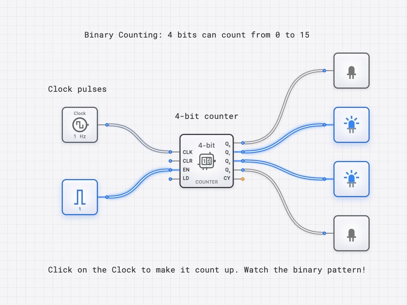 </Figure>Complex Processing Units
<Figure caption="8-bit ALU system capable of performing arithmetic and logical operations on 8-bit data inputs"> 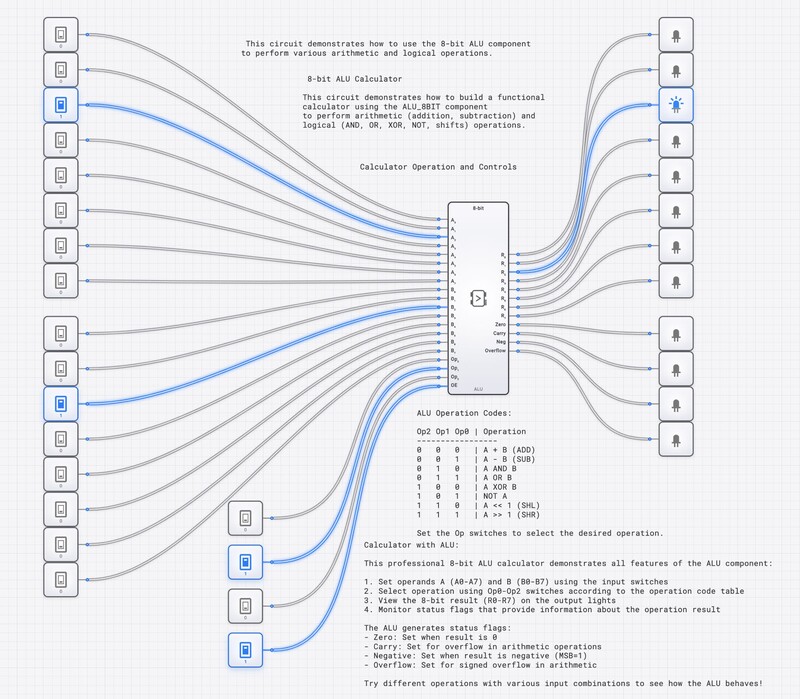 </Figure>Data Management Systems
<Figure caption="Register data transfer system illustrating parallel data loading and serial data shifting operations"> 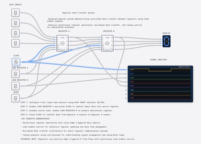 </Figure> <Figure caption="Sequential instruction executor demonstrating program counter, instruction decode, and execution phases"> 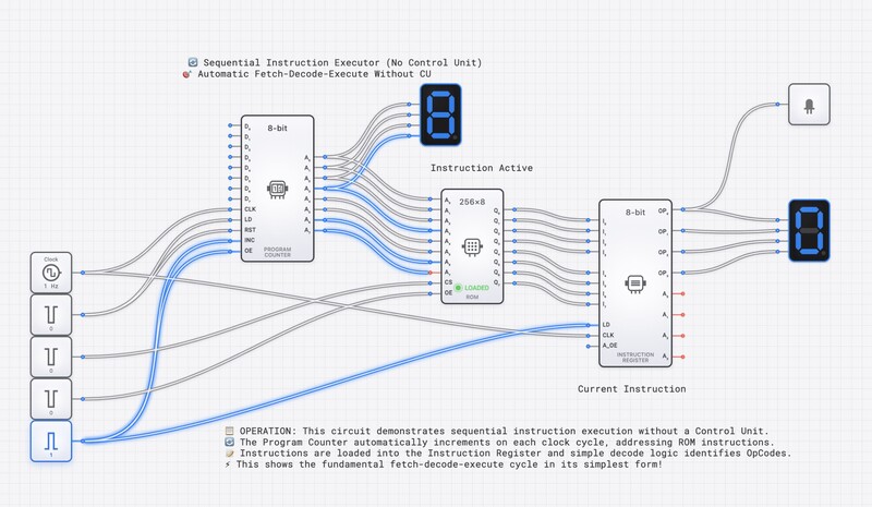 </Figure>Interactive Circuit Demonstrations
Dynamic Addition Process
<Figure caption="Real-time demonstration of 3-bit binary addition showing input changes and immediate output calculations"> <Video src="/images/examples/3-Bit_Binary_Adder.webm" poster="/images/examples/3-Bit_Binary_Adder.jpg" /> </Figure>Asynchronous Counter Operation
<Figure caption="4-bit asynchronous ripple counter showing propagation delay and cascading state transitions"> <Video src="/images/examples/4-Bit_Asynchronous_Ripple_Counter.webm" poster="/images/examples/4-Bit_Binary_Counter.jpg" /> </Figure>Serial Data Processing
<Figure caption="4-bit shift register demonstrating serial input, parallel processing, and data flow through register stages"> <Video src="/images/examples/4-Bit_Shift_Register.webm" poster="/images/examples/Register_Data_Transfer_System.jpg" /> </Figure>Image Organization Structure
public/images/
├── examples/                    # Real digital logic demonstrations
│   ├── AND_Gate_Security_System.jpg      # Basic logic implementation
│   ├── 3-Bit_Binary_Adder.jpg           # Arithmetic circuits
│   ├── 3-Bit_Binary_Adder.webm          # Dynamic adder demo
│   ├── 4-Bit_Binary_Counter.jpg         # Sequential logic
│   ├── 4-Bit_Asynchronous_Ripple_Counter.webm  # Counter animation
│   ├── 4-Bit_Shift_Register.webm        # Data flow demo
│   ├── 8-Bit_ALU_System.jpg             # Complex computational unit
│   ├── Register_Data_Transfer_System.jpg # Memory operations
│   └── Sequential_Instruction_Executor.jpg # Program control
├── articles/                    # Article-specific images
├── tutorials/                   # Tutorial screenshots and demos
├── case-studies/               # Case study visuals
└── shared/                     # Reusable images across content
    ├── icons/                  # Icon library
    ├── logos/                  # Brand assets
    └── patterns/               # Background patterns
Horizontal Rules
Use horizontal rules to create visual separation between major sections:
Emphasis and Strong Text
Combine different emphasis techniques for maximum impact:
- Bold text for strong emphasis
- Italic text for subtle emphasis
- Bold italic for maximum emphasis (use sparingly)
Code formattingfor technical termsBold codefor important technical terms
Special Formatting
You can create various text effects:
Strikethrough textfor deprecated features- <u>Underlined text</u> for special emphasis
- Superscript: E = mc²
- Subscript: H₂O
Future Vision
DigiSim.io continues to evolve as the leading platform for digital logic education, with exciting developments planned to enhance learning experiences and expand educational capabilities.
Roadmap and Development
- Enhanced Component Library - Expanding to include advanced FPGA components and modern processor architectures
- AI-Powered Learning Assistant - Intelligent tutoring system providing personalized guidance and feedback
- Collaborative Design Tools - Real-time multi-user circuit design and team project capabilities
- Advanced Simulation Features - Power analysis, thermal modeling, and electromagnetic compatibility simulation
- Mobile Application - Native iOS and Android apps for circuit design and learning on-the-go
- Virtual Reality Integration - Immersive 3D circuit visualization and manipulation
- Industry Partnerships - Collaborations with leading semiconductor companies for real-world component models
Educational Innovation
<Callout type="tip" title="Next-Generation Learning"> DigiSim.io is pioneering adaptive learning algorithms that adjust content difficulty and pacing based on individual student performance, ensuring optimal learning outcomes for every user regardless of their starting knowledge level. </Callout>Platform Architecture Excellence
DigiSim.io maintains the highest standards in educational technology:
DigiSim.io Platform Structure:
├── Core Simulation Engine/
│   ├── Event-Driven Architecture           # Precise timing simulation
│   ├── Component Library Management        # Scalable component system
│   ├── Real-Time State Visualization      # Dynamic circuit feedback
│   ├── Multi-Channel Oscilloscope        # Advanced debugging tools
│   └── Memory Management System           # RAM/ROM simulation
├── Educational Content/
│   ├── Interactive Tutorials/
│   │   ├── Animated Demonstrations        # Step-by-step learning
│   │   ├── Audio Narration Support       # Accessibility features
│   │   └── Progress Tracking System      # Learning analytics
├── User Experience/
│   ├── Responsive Web Interface          # Cross-platform compatibility
│   ├── Cloud Circuit Storage            # Seamless collaboration
│   ├── Sharing and Collaboration        # Community features
│   └── Assessment Integration           # Educational evaluation
└── Technical Infrastructure/
    ├── Modern Web Technologies          # Angular, TypeScript, SCSS
    ├── Performance Optimization         # Efficient rendering
    ├── Security and Privacy            # Data protection
    └── Scalable Architecture           # Growing user base support
Excellence in Digital Logic Education
✅ DigiSim.io Advantages:
Event-Driven Simulation- Industry-standard timing accuracy50+ Professional Components- Comprehensive learning coverageReal-Time Visual Feedback- Immediate understanding reinforcementCloud-Based Collaboration- Modern educational workflows
🚀 Continuous Innovation:
- Regular component library updates
- Enhanced simulation capabilities
- Improved user experience design
- Expanded educational content
Educational Impact Measurement
<Callout type="success" title="Proven Results"> DigiSim.io's impact on digital logic education is measurable and significant. Our platform consistently delivers improved learning outcomes, increased student engagement, and enhanced teaching effectiveness across diverse educational environments. </Callout>Technical Excellence Standards
DigiSim.io maintains rigorous standards for educational technology:
// DigiSim.io Quality Assurance Framework
class EducationalExcellence {
  constructor() {
    this.standards = {
      simulation: 'industry-grade accuracy',
      accessibility: 'WCAG 2.1 AA compliance',
      performance: 'sub-100ms response times',
      reliability: '99.9% uptime guarantee'
    };
  }

  // Continuous improvement methodology
  enhanceLearningOutcomes() {
    return {
      dataAnalytics: 'student performance tracking',
      adaptiveLearning: 'personalized content delivery',
      feedbackLoops: 'real-time assessment integration',
      qualityAssurance: 'rigorous testing protocols'
    };
  }
}ter performance
  let prev = 0, curr = 1;
  for (let i = 2; i <= n; i++) {
    [prev, curr] = [curr, prev + curr];
  }

  return curr;
};

// Example usage with error handling
try {
  const result = calculateFibonacci(10);
  console.log(`Fibonacci(10) = ${result}`); // Output: 55
} catch (error) {
  console.error('Calculation failed:', error);
}
Accessibility Considerations
- Use semantic headings - Proper H1-H6 hierarchy
- Include alt text - Describe images for screen readers
- Provide context - Don't rely solely on color or position
- Test with screen readers - Ensure content is accessible
SEO Optimization
- Include target keywords naturally in headings and content
- Write descriptive meta descriptions in frontmatter
- Use internal linking to connect related content
- Optimize for featured snippets with clear, concise answers
Conclusion
This standard template demonstrates all available MDX features in the DigiSim blog system. Use it as a reference when creating new content to ensure consistency, professionalism, and optimal reader experience.
Key Takeaways
- Consistency is crucial - Follow established patterns and conventions
- Quality over quantity - Focus on providing value to readers
- Test everything - Verify all code examples and links work correctly
- Stay updated - Keep content current with latest best practices
This standard template is maintained by the DigiSim Content Team. For questions or suggestions, contact us at content@digisim.io.